Safety always on bord?
Set course with KÜS DRIVE for testing driver assistance systems for more road safety
Testing of malfunctioning automated driving functions caused by degradation, manipulation and incorrect repair.
What does the future of periodic technical inspection (PTI) look like for automated, connected and autonomous vehicles?
Sie sehen gerade einen Platzhalterinhalt von YouTube. Um auf den eigentlichen Inhalt zuzugreifen, klicken Sie auf die Schaltfläche unten. Bitte beachten Sie, dass dabei Daten an Drittanbieter weitergegeben werden.
Mehr InformationenDo driver assistance systems in today's vehicles always work reliably during long-term operation?
The scenario
Due to the rapid technical development of vehicles, which is characterized in particular by integrated ADAS (Advanced Driver Assistance Systems), the test content of the PTI must also keep pace with this development in order to continue to ensure maximum road safety.
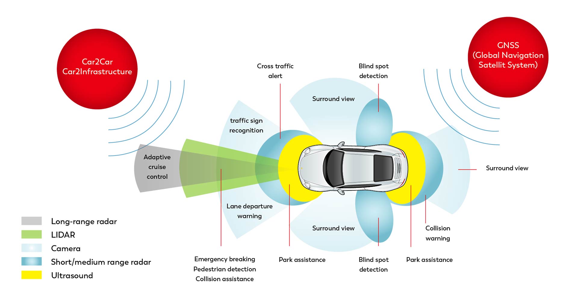
Actual camera sensors are monitoring whether the vehicle is staying in its lane and alerting the driver when it crosses the sidelines. In event the car comes dangerously close to road users ahead, the emergency brake assistant automatically intervenes. Networking communication not only among road users, but also with the traffic infrastructure, will bring safety-related benefits.
The task
Automated driving functions such as the AEBS (Automated Emergency Brake System) emergency brake assistant, which will be mandatory from 2024, are to be checked to ensure they are working correctly. If, for example, emergency braking is triggered at high speed in the overtaking lane of the highway, this faulty function can cause rear-end collisions. The same applies to the classic DAS (Driver Assistance Systems) such as ABS and ESP, which can cause accidents if they malfunction.
To check and ensure correct function over the entire life cycle of the motor vehicle, KÜS is developing a dynamic test procedure. This procedure covers the entire impact chain of the ADAS – from the environment sensors to the evaluation and control unit to the actuators.
Opportunities vs. risks

Accident prevention caused by correct function
In the event of a sudden obstacle or the driver’s attention being reduced, the emergency braking assistant avoids a collision or reduces the consequences of a rear-end collision by automatically applying the brakes.

Risk of accidents due to malfunction
A malfunction of the emergency brake assistant leads to emergency braking that is incomprehensible to the following traffic and thus to possible rear-end collisions.
Automated driving functions
Assistance systems (ADAS)
- Adaptive cruise control (ACC)
- Lane Keeping Assist (LKA)
- Traffic Sign Recognition with Intelligent Speed Adaption (ISA)
- Blind Spot Warning (BSW)
- Adaptive Cruise Control (ACC)
- Automatic Emergency Braking System (AEBS)
- Adaptive Light Beams (AFS)
Technical requirements
- Reproducible measurement results of the impact tests traceable to national normals.
- Testing in a hall with optimized space requirements, i.e. independent of weather conditions.
- Dynamic, freely editable, scenario-based impact tests at speeds above 60 km/h.
- Execution via OTA (Over the Air) stimulation, i.e. without ADAS ECU communication.
- High automation of the impact test to minimize cycle time.
Technical solution
Safe throughout the entire vehicle life cycle
Automated vehicles are capable of recognizing their surroundings and driving semi-autonomously. But how can the functional safety of these vehicle components be guaranteed over the entire vehicle life cycle?
Scenario-based impact principle tests according to the OTA method
The environmental sensors of a vehicle are stimulated contact-free and without access to the relevant ADAS ECU’s. The testing in regard to the impact principle testing investigates the reaction of a technical complete system to a known defined stimulation and evaluates the difference of the complete system’s reaction with the target reaction. In the case of impact testing of driver assistance systems, this means that the stimulation takes place physically (over the air) directly via the ADAS sensors, as on the road. This avoids direct access to the ADAS ECU’s, which makes it possible to check the entire chain of effects.
Tests with contactless sensor stimulation using physical input variables such as video, radar, LiDAR, ultrasound or light waves is referred to as over the air (OTA) testing.
OTA stimulation of the vehicle's sensors
For valid and reproducible results, the vehicle-in-the-loop (VIL) simulation method is used, in which a real vehicle is tested in a virtual environment. This form of validation can be used not only in periodic technical inspections (PTI), but also in end-of-line tests in automotive production and in the R&D sector.
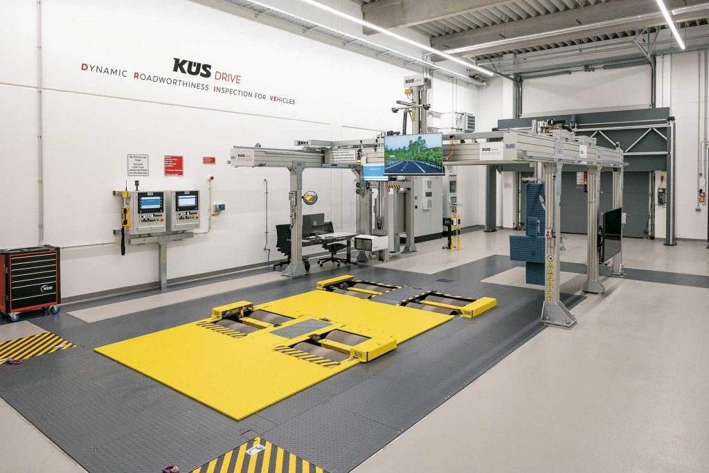
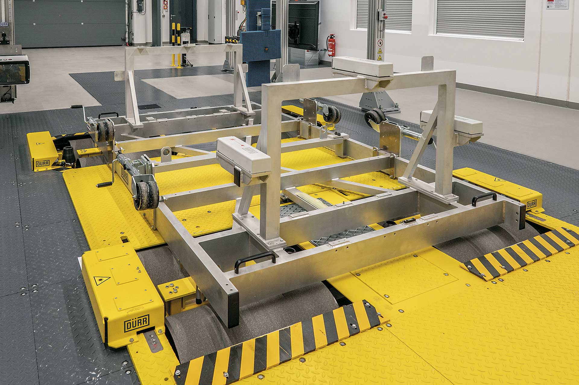
During the VIL test, the vehicle is located on the steerable function tester (SFT) – Dürr’s brand name „x-road curve“ – and is able to accelerate, brake or steer to the right and left under the driver’s control depending on the test scenario to be run.
Due to the technical properties of the steerable function tester, the vehicle always remains positioned longitudinally in relation to the test bench’s axis of symmetry and can be driven at speeds of up to 130 km/h.
Using the software interface between the steerable function tester and the dSPACE toolchain, it is possible to transfer the vehicle’s real physical movements to a digital shadow. This, together with the vehicle environment, is computed in real time on a simulator from dSPACE. The simulation feeds a monitor and a radar target simulator for OTA stimulation of the camera and radar sensors.


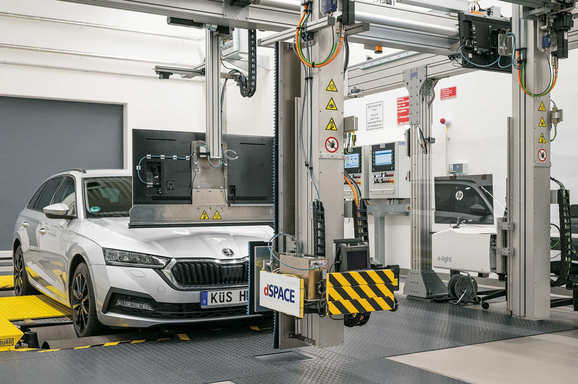
Test setup of the sensor system
A monitor and a radar antenna are integrated into the test line directly in front of the vehicle under test, which can be positioned horizontally and vertically. The monitor stimulates the vehicle’s camera with environmental and road scenarios, which are animated by the sensor-realistic simulation solution AURELION as a 3D world. This serves to verify whether the camera sensor of the VUT („vehicle under test“) correctly detects the relevant objects. The correct function of the lane keeping assistant (LKAS) and the lane departure warning system assistant (LDWS) or also the traffic sign recognition with intelligent speed adaptation (ISA) is tested with realistic road visualizations.
To test the radar sensor, the antenna of the radar target simulator DARTS (dSPACE Automotive Radar Test Systems) is positioned directly in front of the sensor. DARTS emits the radar reflections of a simulated target object. The reflection waves reflect the distance, size, and speed of the object and thus stimulate the radar sensor. This enables reproducible testing of adaptive cruise control (ACC) and emergency brake assist (AEB), which is safe for the test engineers. The homogeneous and coordinated hardware and software components of the test bench thus enable a stable test sequence in real time. If required, test cases can be reproduced exactly to demonstrate the successful elimination of errors.
KÜS DRIVE test scopes

- Dynamic brake testing on two axes at the same time
- Dynamic effective testing of ABS, ESP, ASR (introduction of forces/speeds per wheel)
- Dynamic effective testing of ADAS, i.e. ISA, AEBS, LDW, LKA, ACC
- Dynamic effective testing of the setting of adaptive lighting systems (AFS)
- Testing ADAS up to automated/connected/autonomous vehicles
With its hardware, software and application know-how, KÜS creates KÜS DRIVE based on the various components as a high-performance, future-proof overall concept.
Application example
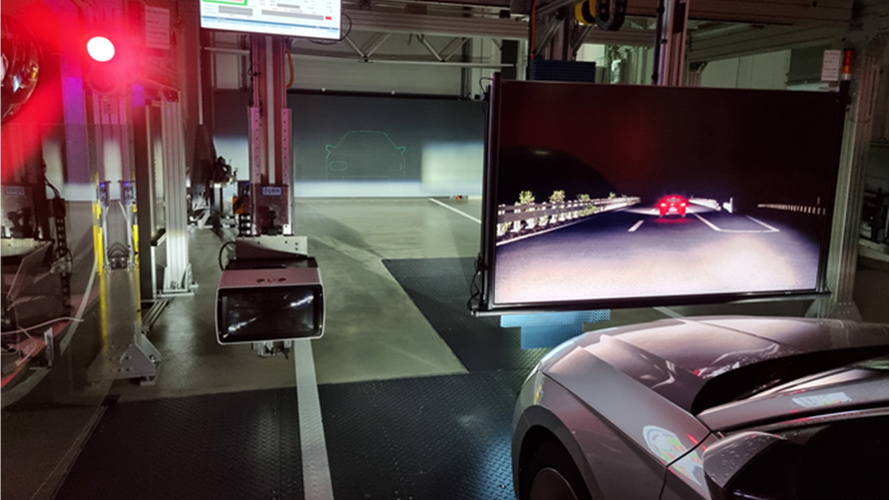
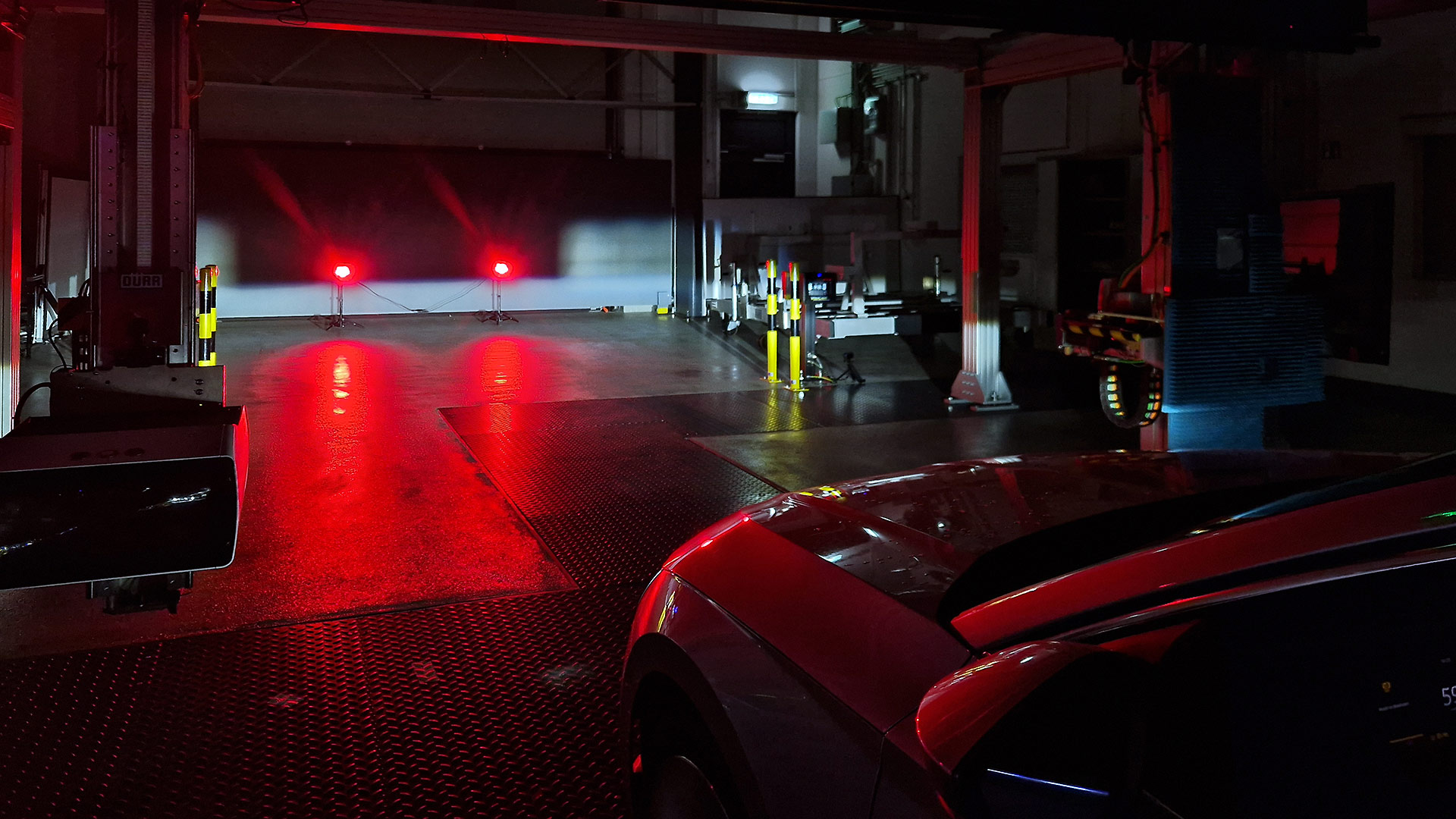
Testing the adaptive lighting systems (AFS)

Functionality
The vehicle drives at speeds of over 60 km/h at night, detects oncoming and preceding vehicles with its camera and fades them out from the side in the potential glare range when the high beam is switched on (see picture aside).
Test Requirements
Test method 1 – by means of environmental simulation
Test method 2 – using LED lights
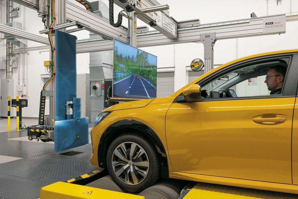
Testing the intelligent speed assistance (ISA)
Functionality
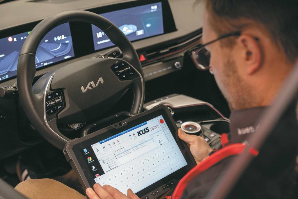
The vehicle passes a traffic sign with a speed limit while driving. This is detected by the vehicle camera and displayed in the cockpit. If the speed limit is exceeded, the driver is notified of the speeding by means of a visual, acoustic or haptic signal.

Test Requirements
The vehicle drives on the SFT and the vehicle camera is played through the monitor with the environment simulation. In the environment simulation, signs are implemented at the edge of a straight road in a freely editable manner. Furthermore, a camera that detects the cockpit and positions other sensors in the vehicle to both check the display of the correct sign and record the warning signals. The camera in the vehicle can be synchronized with the environment simulation.
Test Method
The time at which the front axle of the digital image of the vehicle passes the sign in the environment simulation is compared with the time when the sign appears in the cockpit. The test criterion is the time difference between passing the blade and the correct display of it in the cockpit.
Please also see the accompanying video.
Detailed descriptions of tests and their results can be found in the publications below.
Publications
- «Impact testing of dynamic safety-relevant driving functions within the periodic vehicle inspection»
- «ADAS impact tests of plated vehicles based on the ViL test concept Motivation, preconditions and results»
- «Optimization of the intelligent speed assistant (ISA) homologation by a special Vehicle-in-the-Loop (ViL) test bench with environment simulation»
- «ADAS performance reduction by misaligned environment sensors of plated vehicles»
- «A Vehicle-in-the-Loop Approach for Front Camera Verification Using Adaptive High Beam»
Results and outlook
Adaptation of PTI to automated, connected and autonomous vehicles
Legally required main inspections not only help to prevent technical malfunctions, but they also increase road safety. Additionally, ADAS driver assistance systems are capable of significantly reducing accidents caused by human error or incapacity. In order to ensure this, however, these systems must perform faultlessly over the entire vehicle life cycle. Possible disruptive factors in this context are:
- Aging of materials and components
- Inadequate or faulty repairs or maintenance
- Component and system manipulation
- Illegal or excessive tuning
- Limitations of self-diagnosis
Recognizing technical defects and thus preserving road safety is ensured, among other things, by periodic testing.
For example, adaptive cruise control (ACC) and emergency brake assist (AEB) can prevent rear-end collisions even at high speeds and so contribute significantly to reducing the number of accidents.
Particularly in these accidents, in which a moving vehicle collides with a vehicle traveling in the same direction or a stationary vehicle, fatalities and serious injuries often occur in addition to high property damage. However, erroneous activation of an incorrectly set emergency brake assistant also can lead to rear-end collisions.
PTI of safety systems
In the course of developments in the automotive sector, it is evident that the significance of driver assistance systems is changing. While they were initially comfort systems that made it easier for the driver to be in control of the car, they are increasingly developing into safety systems. From this point of view, it becomes clear how indispensable it is to include these systems in the framework of periodic vehicle inspections and to create the legal basis for this.
The KÜS DRIVE test lane already demonstrates a convincing concept for a technical solution to the new requirements for the scope of testing in the regular main inspection for automated vehicle functions. The safety of automated driving functions can be tested and validated in appropriately equipped test centers over the life cycle of a vehicle.

With KÜS DRIVE, we are working on tommorrow’s innovations to push forward solutions for improved vehicle safety and the functional reliability of assistance systems and automated driving throughout the entire product life cycle.
Dipl.-Ing. Peter Schuler
Chief Executive Officer of KÜS
Focused on the future
KÜS early recognized that rapidly evolving and increasingly automated vehicles are introducing new safety issues that need to be addressed for road-legal vehicles. In order to keep pace with this technological progress in the field of driver assistance systems, the requirements for periodic vehicle monitoring regulated by law are increasing steadily as a consequence.